
This project is designed to measure and report the water level in a water tank with a closed top – typically as used for water storage on a farm. These tanks are generally made from PVC and are filled by a windmill or electric pump from an underground aquifer or other water source. Tanks range in size, but are typically 2 metres high and 4 metres in diameter.
The following design requirements have been considered.
- Must operate unattended for long periods (target at least one year) using only batteries. This is intended to be the sole power source, so low power is a key requirement.
- Ideally it should report the water level every hour, but if power proves to be an issue, this could be relaxed to every few hours. At worst case recordings could be made once per day.
- The LoRaWAN must be used for the wireless uplink. This constrains the actual payload volume based on the duty cycle of LoRaWAN. Connection will be to The Things Network.
- Related metadata such as enclosure temperature and humidity and battery status must also be reported.
- Data storage and visualisation will be via InfluxDB and Grafana (as are used in other projects).
General Operation
The project uses a PyCom LoPy4 module connected to a MaxBotix ultrasonic distance sensor. The sensor is mounted in the top of the tank and points vertically at the water surface. The ultrasonic sensor measures the distance from the sensor to the top of the water. This is used to calculate the water level. The sensor used can (according to the specification sheet) measure distances from 300 mm to 5000 mm. This sensor was chosen as tanks are generally about 2000 mm high, so fit in the mid range for this sensor type.
The tank top is generally peaked, with a support pole up through the centre. The sensor is mounted close to the centre of the top, in an attempt to maximise the distance between the water level when the tank is full, and the sensor itself. Ideally this distance should exceed 300 mm. The sensor should not be mounted too close to the centre of the top to ensure the internal support pole does not interfere with the ranging.
Data is collected by querying the sensor to retrieve the measurement. This measurement along with related metadata is transmitted via LoRaWAN. The related metadata includes temperature and humidity reading from inside the enclosure, light level inside the enclosure and battery voltage.
The LoPy4 module is placed in deep sleep once the measurements are taken and transmitted. It wakes from deep sleep based on a timer.
The PyCom Module
This project uses the LoPy4 module. This module supports multiple wireless communication stacks. This project utilises only the LoRaWAN stack. The other communications stacks are deliberately disabled to conserve battery power.
The pin numbers on the module are referenced using both hardware module pin numbers and Pxx numbers. The Pxx numbers are Pin Names. They should not be confused with actual pin numbers. Both are shown in the Module Connections table below.
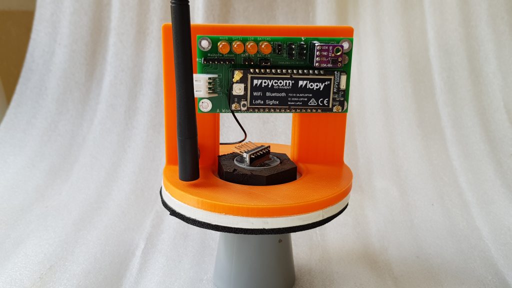
The following image show the assembled LoPy4 module mounted on the custom PCB. The PCB mounts on the insert frame before being lowered into the housing. The mounting bracket and housing are 3D printed. The exterior of the housing is painted with UV protective paint and clear lacquer.
The Enclosure Hardware
The electronics is contained within a small 3D printed cylindrical enclosure mounted on top of the tank. A horizontal divider separates the enclosure into two chambers. The lower chamber contains the sensor and is directly exposed to the tank and is therefore subject to higher humidity. The upper chamber contains just the electronics and is intended to be ambient humidity. The sensor mounting plate (the white layer in the above image) uses a rubber seal on the bottom to help restrict the humidity level in the upper electronics enclosure.
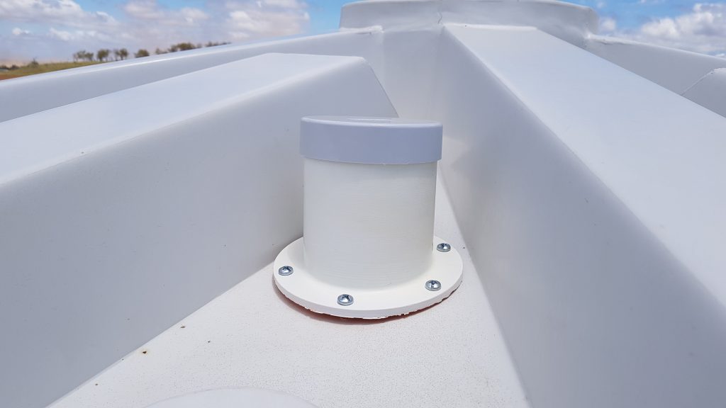
The flange on the enclosure is screwed to the top of the tank. A commercially sourced press fit lid is used to weatherproof the enclosure. A hole (approximately 50 mm diameter) must be cut (using a hole saw) through the top of the tank to permit the sensor to point vertically downwards through this hole. The angle of the flange is made to match the slope on the tank top to ensure the sensor points vertically.
The LoRaWAN Data Payload
As well as the water level measurement, a number of other measurements are taken and reported. As the data payload using LoRaWAN has to be minimised, the various numeric values are stored as hex values rather than ASCII strings. The various data elements are as follows.
- A transmission sequence number.
- Water level. This is the distance in millimetres from the sensor to the top of the water.
- Temperature (in degrees Celsius) inside the electronics enclosure.
- Relative Humidity inside the electronics enclosure. The humidity level may affect the electronics, so this must be monitored.
- Battery voltage. The battery level is monitored as an indicator when to replace the batteries.
- Ambient light level inside the electronics enclosure. The internal ambient light level is used to confirm the enclosure remains intact and closed. Any light entry suggests the lid has been removed, or the enclosure has been otherwise damaged. This is simply a raw value from the sensor mapped to an 8 bit value.
The following table details the message payload.
| Element No | Data | Data Type | Data Length |
|---|---|---|---|
| 1 | Sequence Number | Sequence number increments on each entry to deep sleep. | 16 bit |
| 2 | Water level | Distance reported by Maxbotix sensor in mm. (Valid range is 300 to 5000). | 16 bit |
| 3 | Enclosure Temperature | Temperature in degrees Celsuis. Realistic values range from just below zero to about 40. To retain granularity and minimise the size, the reading is incremented by 100 and then multiplied by 10. | 16 bit |
| 4 | Enclosure Humidity | Relative humidity in the range 0-100. Realistic values around 60-90. | 8 bit |
| 5 | Battery Voltage | Battery voltage from measurement divider, mapped to a range 1-256. Calculation required to determine actual voltage. | 8 bit |
| 6 | Enclosure Ambient Light Reading | Raw sensor reading mapped to range of 1-256. Only intended to indicate light (enclosure open) or dark (enclosure intact). | 8 bit |
Maxbotix Sensor Connections
The MaxBotix ultrasonic sensor provides several ways to retrieve the measurement data. These include analog output, digital pulse width and serial data. This project uses serial data which is received by one of the UARTs on the PyCom module.
The following table shows the pin connections for the MaxBotix sensor harness. This harness connects the sensor to the interface board. Click here for the Maxbotix data sheet showing pin details.
| Maxbotix Pin Number | Term | Wire Colour | P1 Interface Board Pin Number | Comment |
|---|---|---|---|---|
| 1 | Temperature Sensor Connection | NC | Unused. No connection in harness | |
| 2 | Pulse Width Output | White | 3 | Unused in this project. |
| 3 | Analog Voltage Output | Green | 5 | Unused in this project. |
| 4 | Ranging Start/Stop | Purple | 4 | Unused in this project. |
| 5 | Serial Data (Sensor output) | Yellow | 2 | Connects to RX2 on PyCom module. |
| 6 | Vcc | Red | 6 | The sensor is driven by 3.3V from a digital I/O line (P21) on the PyCom module (rather than from the 3.3 V supply. |
| 7 | Ground | Black | 1 |
Power Management
This project is intended to operate from batteries and to run for (optimistically) a year or more from a single set of batteries. This necessitates minimal power consumption.
The following power consumption has been measured.
- LoPy4 module in normal operation About 120 mA
- Maxbotix sensor About 2.5 mA (while transmitting serial data).
- When the LoPy4 module is put into deep sleep (using something like “machine.deepsleep(int(time_to_sleep))” the power consumption drops to about 20 uA. This is measured in series with the power input delivered by three AA batteries in series to provide about 4.5 V.
- Interesting things happen when the USB to Serial debug console is connected to the LoPy4 module. Despite taking power from the USB connection, this device impacts power consumption on the module itself. When both TX and RX are connected, the deep sleep power only drops to about 18 mA. When either the TX or RX leg is connected, deep sleep power sits at about 40 mA.
- Sensors (including the Maxbotix sensor) are powered from digital I/O pins on the micro controller. This allows each sensor to be powered up in sequence as needed to perform the required measurement. Low power sensors have been chosen so this capability can be used. After a sensor is powered up, some stabilisation time (usually about one second) is allowed in case any stabilisation is needed. As each measurement is taken, the sensor is again powered down.
PyCom LoPy4 Module Connections
The following pin connections are used on the LoPy4 module. This shows all external connections as used by the sensors, the power supply and the serial console which may be connected for debug purposes.
| Module Pin No | Pin Name | Term | Usage |
|---|---|---|---|
| 1 | Reset | ||
| 2 | P0 | ||
| 3 | P1 | ||
| 4 | P2 | ||
| 5 | P3 | TX1 | Serial console. Connects to USB Serial module for debug output. |
| 6 | P4 | RX1 | Serial console. Input not currently supported, but connected anyway. |
| 7 | - | ||
| 8 | - | ||
| 9 | - | ||
| 10 | P8 | TX2 | Serial TX for UART2. Not used in this project. |
| 11 | P9 | SDA | i2c for SHT31 sensor. |
| 12 | P10 | SCL | i2c for SHT31 sensor. |
| 13 | P11 | RX2 | Serial RX for UART2. Used as RX for serial data from Maxbotix sensor. |
| 14 | P12 | ||
| 15 | P13 | ||
| 16 | P14 | ||
| 17 | P15 | LDR Sense (from LDR voltage divider) | |
| 18 | P16 | Battery Sense (from battery voltage sense voltage divider) | |
| 19 | P17 | ||
| 20 | P18 | ||
| 21 | P19 | ||
| 22 | P20 | Battery sense switch enable. This controls the switch in the MAX4645 analog switch IC. | |
| 23 | P21 | p_maxbotix_power | Power (3.3v) to Maxbotix sensor. |
| 24 | P22 | p_sht31_power | Power (3.3v) to SHT31 sensor. |
| 25 | P23 | Power (3.3v) to LDR voltage divider. | |
| 26 | +3.3v regulated output | Provides permanent power to the MAX4645 analog switch. | |
| 27 | Ground | ||
| 28 | Voltage input | Input supply to the LoPy4 board from external voltage source. (Battery pack) |
Environmental Monitoring
The following environmental parameters are monitored by the LoPy4 micro-controller. This metadata is transmitted as part of the LoRaWAN payload.
- Enclosure temperature and humidity.
- Ambient light.
- Battery voltage.
To minimise power consumption, these sensors are powered up only when needed. As these are generally low power devices, they are driven directly by a digital I/O pin from the module. The battery voltage sensing uses a simple voltage divider with an analog switch used to complete the circuit to ground. This ensures the battery voltage sensing circuit is only drawing power when a measurement is needed. The analog switch itself remains powered.
Sensors Used
The following sensors are used in this project.
| Sensor Function | Sensor Model | Details |
|---|---|---|
| Water level sensor | MaxBotix HRXL 7380 | This ia an ultrasonic device which measures the distance (300 mm - 5000 mm) between the sensor and the water surface. The serial interface is used. |
| Temperature and humidity sensor | Sensirion SHT31 breakout module (generic module) | This connects via I2C to the controller. |
| Ambient light sensor | Generic LDR with a resistance range between about 100 ohms in sunlight and 100K ohms in darkness. | A voltage divider is used to create about 3.0 V under full light. |
| Battery voltage sensor | This is another simple voltage divider setup to create about 3.0 V when the battery supply is at the peak value of 4.5 V. | This circuit uses an analog switch to complete the circuit through the voltage divider to GND. The analog switch is controlled by a digital I/O pin from the PyCom module. To prevent continuous battery drain, the voltage divider circuit is only enabled when the sensor reading is made. |
Resources
Future Enhancements
Some Future Enhancements are proposed for this project.